Overview
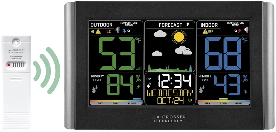
I used a 433MHz radio receiver and transmitter with an Attiny chip to interface an AcuRite weather transmitter with a La Crosse weather display. I own a La Crosse weather transmitter and station. Several years ago, my transmitter stopped working. It wasn’t until recently when I began working on another project that I discovered a wireless weather transmission coming from nearby.
Code Creation
Receive Acurite
Using a RTL-SDR with the “rtl_433” program, I was able to see that someone owned a weather station in the general vicinity.
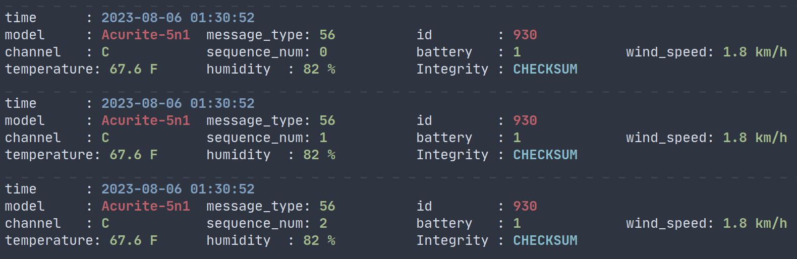
From the output, my neighbor owns an AcuRite 5-in-1 weather sensor. This device transmits temperature, humidity, wind speed, wind direction, and rainfall on the 433MHz frequency. Every 30 seconds, an AcuRite transmitter will send 3 identical messages (not including the sequence number). An AcuRite weather station (usually some sort of display) will demodulate and process the received data into a handy human-readable display.
Demodulation
To receive AcuRite data using an arduino (or attiny chip), a 433 MHz receiver must connect to the microcontroller. I will be using the RC Switch library, which can be used send and receive RC codes.
#include <RCSwitch.h>
RCSwitch receiver = RCSwitch();
---snip---
void receive() {
  receiver.enableReceive(0);  // Receiver on interrupt 0 => that is pin #2
  static const RCSwitch::Protocol acurite = { 204, { 3, 3 }, { 2, 1 }, { 1, 2 }, false };
  receiver.setProtocol(acurite);
  while (!receiver.available()) {};
  receiver.resetAvailable();
---snip---
The receive() function first enables the receiver on pin #2. In order to differentiate an AcuRite transmission from random noise, the protocol uses Pulse Width Modulation. As a quick AcuRite PWM crash course, data is read one bit every clock cycle. In each cycle, a digital 1 is represented by a short pulse, and a digital 0 is represented by a long pulse. Thanks to rtl_433, we are able to visualize the pulsedata coming from Acurite.
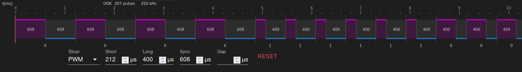
As shown above on the right side, a bit is read every 612ms.
Note: There is a margin of error for received pulse data. I set the pulse length to two short pulses equal one long pulse.
    __
0: |  |_ : long high pulse (~408ms), short low pulse (~204ms)
    _
1: | |__ : short high pulse (~204ms), long low pulse (~408ms)
The acurite protocol definition is in the format: {pulselength, Sync bit, “0” bit, “1” bit, invertedSignal}. Given that each bit is composed of 3 short pulses (204ms * 3 = 612ms):
| pulselength | 204ms |
| Off bit | {2,1} #2 high pulses, 1 low pulse |
| On bit | {1,2} #1 high pulse, 2 low pulses |
| sync header | 3 high pulses and 3 low pulses x4 (612ms up, 612ms down) x4 |
| invertedSignal | false |
Decoding
As mentioned before, 3 near-identical messages are released every 30 seconds. Here is an example message set:
[01] {65} 03 a2 78 00 88 36 d2 ad 00
[02] {65} 13 a2 78 00 88 36 d2 bd 00
[03] {65} 23 a2 78 00 88 36 d2 cd 00
Once again, the rtl_433 repository proves invaluable with the Acurite data decoding. The acurite.c that exists in the rtl_433 repository demonstrates the decoding process of an Acurite message.
{65} 03 a2 78 00 88 36 d2 ad 00
 ^^ sync byte (in buf as item 0)
     ^^ ^^ ^^ id, seq, status, etc
              ^^ ^^ wind speed
                 ^^ ^^ temperature
                       ^^ humidity
  void receive() {
  ---snip---
  if (b[3] & 0x3f == 56){ //correct message type
      bool failure = false;
      int temp_raw = (bb[5] & 0x0F) << 7 | (bb[6] & 0x7F);
      float tempf = (temp_raw - 400) * 0.1f;
      uint8_t humidity = (bb[7] & 0x7f);
      if (humidity < 0 || humidity > 100 || tempf < -40 || tempf > 158) {failure = true}; //data sanity
  }
  ---snip---
Transmit La Crosse
Now that we have temperature and humidity stored in a variable, it is time to transmit the data to the La Crosse weather station. I emulated the La Crosse TX141TH-Bv2 sensor. From the description in lacrosse_tx141x.c, we can gather a PWM profile for rc-switch:
RCSwitch transmitter = RCSwitch();
void transmit(float tempc, int humi) {
  transmitter.enableTransmit(2); //arduino pin #10
  transmitter.setRepeatTransmit(1); //disables repeat
  static const RCSwitch::Protocol sync = { 833, { 0, 0 }, { 1, 1 }, { 1, 1 }, false };      //833ms apart
  static const RCSwitch::Protocol lacrosse = { 208, { 0, 0 }, { 1, 2 }, { 2, 1 }, false };
---snip---
I created a different protocol for the sync header because the preamble is 833ms high and 833ms low repeated 4 times. RCSwitch does not allow repeated sync packets, so I used a different protocol for sync. Following the La Crosse transmission analysis, the protocol can be coded as such:
[id] [id] [flags] [temp] [temp] [temp] [humi] [humi] [chk] [chk]
Every 4 bits of data is enclosed in [ ] for a total of 40 bits.
---snip---
    transmitter.setProtocol(sync);
    transmitter.send("1111");  //initial sync of 4x 833us high and low
    transmitter.setProtocol(lacrosse);
    transmitter.send(0xFF, 8);       //bogus nonzero ID;
    transmitter.send("1001");        //flags: battery 0 (!1), test 0, channel 01
    transmitter.send(temp_raw, 12);  //12 bit packet
    transmitter.send(humi, 8);       //8 bit packet
    transmitter.send("11111111");    //dummy CRC is unchecked
---snip---
According to rtl_433, “The TX141TH-Bv2 sensor sends 12 of identical packets, one immediately following the other, in a single burst. These 12-packet bursts repeat every 50 seconds”. The final transmission function is shown below:
void transmit(float tempc, int humi) {
  transmitter.enableTransmit(2); //arduino pin #10
  transmitter.setRepeatTransmit(1); //disables repeat
  static const RCSwitch::Protocol sync = { 833, { 0, 0 }, { 1, 1 }, { 1, 1 }, false };      //833ms apart
  static const RCSwitch::Protocol lacrosse = { 208, { 0, 0 }, { 1, 2 }, { 2, 1 }, false };

  int temp_raw = tempc * 10 + 500; //converts Celcius to La Crosse 12 bits

  for (int i = 0; i < 12; i++) { //12 repeated packets
    transmitter.setProtocol(sync);
    transmitter.send("1111");  //initial sync of 4x 833us high and low
    transmitter.setProtocol(lacrosse);
    transmitter.send(0xFF, 8);       //bogus nonzero ID;
    transmitter.send("1001");        //flags: battery 0 (!1), test 0, channel 01
    transmitter.send(temp_raw, 12);  //12 bit packet
    transmitter.send(humi, 8);       //8 bit packet
    transmitter.send("11111111");    //dummy CRC is unchecked
  }
  transmitter.setProtocol(sync);
  transmitter.send("11");  //post-amble 2x 833us high and low
  transmitter.disableTransmit();
}